Walk any major trade show floor today — CES, EXHIBITORLIVE, Pack Expo — and LED video walls appear in nearly every mid-sized booth and virtually every large-scale island exhibit. Direct-view LED has moved from luxury specification to default expectation in less than a decade. The problem isn't the technology. The problem is that most of the content about LED walls for trade shows is written by AV vendors, not fabricators. The structural, electrical, and thermal realities of integrating a 20-square-meter LED wall into a custom exhibit build are poorly documented from the fabrication side. That gap creates expensive surprises.
LED Wall Basics Every Fabricator Must Know
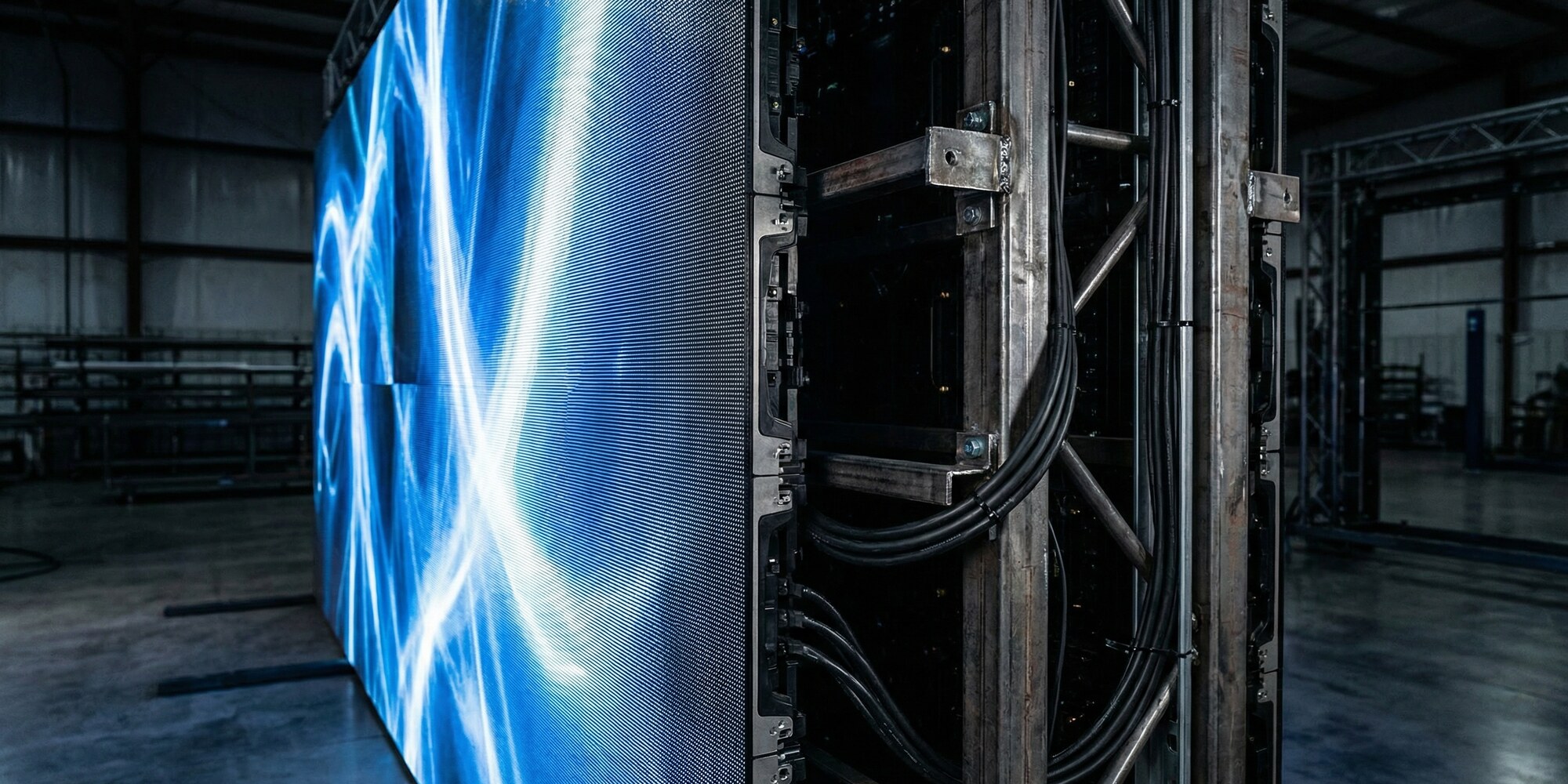
Before the first drawing is cut, a fabricator needs to understand what an LED wall actually is at the hardware level. Direct-view LED panels consist of individual cabinets — typically 500×500mm or 500×1,000mm — that tile together to form a seamless display surface. Each cabinet contains thousands of individual LED clusters (pixels), and the density of those clusters determines the pixel pitch: the distance in millimeters between pixel centers. A 2.5mm pixel pitch panel looks sharp from eight feet; a 6mm panel is appropriate for distances of 20 feet or more. Fabricators who don't ask the AV vendor for the pixel pitch spec before designing the wall housing are building without critical information.
Weight is the other number that matters before design begins. Indoor direct-view LED cabinets typically weigh between 12 and 20 kilograms per square meter, depending on cabinet construction and pixel pitch. A 15m² wall — not unusual for a 20x20 island exhibit — can weigh 180 to 300 kilograms. That weight must be supported by the exhibit structure, and the exhibit structure must be designed to carry it from the start. Structural assumptions that get changed after millwork drawings are finalized don't get changed cheaply.
Power consumption follows a similar logic. LED walls operating at full white typically draw 300 to 600 watts per cabinet. A 20m² installation with 500×1,000mm cabinets (40 cabinets total) can draw 12,000 to 24,000 watts at peak load — though actual content rarely saturates to that level and derate factors typically reduce real-world consumption by 30 to 50 percent. Still: the electrical rough-in must be sized for the worst case, not the average.
Structural Engineering for Heavy Display Hardware
The structural challenge of LED wall integration is real and frequently underestimated by shops new to the specification. Three mounting approaches are common in exhibit environments: floor-supported frames (most common), rigging from venue overhead structure (requires venue structural approval and dedicated rigging points), and integration into the exhibit architecture itself — embedding the LED wall into a tower, header, or curved wall structure.
Floor-supported frames are the most controllable option for fabricators. A properly engineered floor frame for a large LED wall typically uses 2-inch square steel tube welded into a braced rectangular grid, with a dead-load safety factor of at least 4:1 applied to the LED wall's rated weight. Lateral bracing matters for tall, narrow walls — an 8-foot-high, 4-foot-wide LED column is a different structural problem than a wide horizontal field. Shops that fabricate their own steel frames for LED walls have a significant advantage over those who depend on aluminum extrusion systems borrowed from truss-and-panel exhibit structures; extrusion systems can carry the load but often lack the rigidity needed to keep the LED cabinet array perfectly planar under show-floor conditions.
"A fabricator who builds a structure that requires disassembly to swap a failed cabinet earns a show-floor reputation that takes years to overcome."
For LED walls integrated into exhibit architecture — built into a column, flush with a curved wall, embedded in a header — the fabricator must coordinate closely with the AV vendor on cabinet mounting hardware. Most LED cabinet systems attach via a combination of hanging brackets (top-hung, supported from a horizontal rail) and alignment pins. The rail must be bolted through the exhibit skin into the structural backing frame, not just face-fastened to millwork. The tolerances required for LED cabinet alignment are tighter than standard exhibit construction: cabinets that are out of plane by more than a few millimeters create visible seams at show distances. Shops like Innovate 3D, which combines in-house CNC routing with structural fabrication capabilities, are well positioned to hold these tolerances because the same shop that cuts the mounting frame also assembles and checks it before the wall goes anywhere near a show floor.
Power Rough-In and Electrical Coordination
The fabricator's electrical scope on an LED wall integration is infrastructure, not AV. The scope includes: conduit routing from the exhibit's main power entry point to the LED wall location, junction box placement and sizing for the LED power supply units, cable management channels sized for the LED wall's data and power cabling runs, and coordination with the exhibitor's electrical show order so the right circuit capacity arrives at the booth.
Cable management is the detail that distinguishes professional LED wall integrations from improvised ones. LED wall installations generate thick cable bundles — each cabinet requires both power feeds and data signal cables (typically RJ45 or fiber, depending on the system). Those bundles have specific minimum bend radius requirements that vary by manufacturer; violating them causes signal errors and hardware failures. The fabricator who builds a cable chase that's too narrow, or routes power and data cables through the same conduit as venue power drops, creates problems that don't show up until tech rehearsal on Tuesday morning.
The exhibit's main power entry point should be specified to match the LED wall's actual power draw plus a 20 percent buffer for other exhibit electrical loads. A 20m² LED wall at moderate content load typically requires a 60 to 80-amp, 208-volt circuit dedicated to LED power supply units alone. Shops that order a 30-amp circuit because that's what their standard single-deck exhibit uses are planning for a venue service call that will cost more than upgrading the order would have.
Thermal Management: The Problem That Shows Up on Day Two
Indoor LED cabinets generate heat in operation. Most are passively cooled — heat dissipates from the rear of the cabinet through convection. This works adequately in open-air installations. It fails in exhibit structures where the LED wall is embedded in a tight architectural enclosure that traps heat behind the panel array.
The failure mode is consistent: the exhibit looks perfect during setup on Monday, runs through Tuesday with increasing cabinet temperatures, and shuts down a section of the wall mid-afternoon Wednesday when the thermal protection circuits trip. This is not an LED wall defect; it is a fabrication design defect. The exhibit structure didn't provide adequate convective airflow behind the panels.
The fix is straightforward when designed in from the start: ventilation cutouts in the rear wall or base of the LED wall housing, sized to allow natural convection to carry heat away from the cabinet backs. For fully enclosed column or tower structures, convection alone is often insufficient and active cooling — a small fan or HVAC mini-split serving the enclosed equipment space — must be specified. The AV vendor will provide thermal specifications for the specific cabinet model; the fabricator's job is to design around them, not assume the hardware will tolerate whatever environment it's placed in.
Serviceability: Build for the Swap
Individual LED cabinets fail. It's not common, but it happens — a damaged pixel cluster, a failed power supply unit, a connector that loosens in transit. When a cabinet fails on the show floor, the exhibitor's AV team needs to swap it in under 30 minutes without disassembling surrounding exhibit components.
Front-access mounting — where the LED cabinet can be removed from the front of the wall by releasing its hanging brackets, without touching anything behind it — is the professional standard. Some exhibit designs make front access impossible: the LED wall sits flush against a backdrop wall with no clearance for a technician to work from behind, and the front face is the only access. In that scenario, the mounting hardware must allow front-panel removal. The fabricator who builds a structure where swapping a cabinet requires removing adjacent millwork, cutting access panels, or disassembling structural components is creating a liability.
Maintenance lane clearances matter for column-integrated or tower-integrated LED walls. A minimum 24-inch clear zone behind or beside the LED structure — even if that zone is behind a lockable access panel — gives service technicians the physical space to work. Fabrication shops that consistently build serviceable LED structures get called back. Those that don't get replaced on the next project.
The AV Vendor Coordination Protocol
The most reliable predictor of a successful LED wall integration is early, structured coordination between the fabricator and the AV vendor — ideally before the fabrication drawings are finalized. The minimum information a fabricator needs before cutting anything is: the approved cabinet layout drawing (size, configuration, and the mounting hardware spec for the specific cabinet model), the power distribution diagram (number of power supply units, their physical dimensions, and their mounting locations), the data signal path (where the processor lives, cable routing requirements from processor to first cabinet), and the total installed weight.
Projects where the fabricator and AV vendor don't connect until the week of installation are the projects that end badly. A 3D printing and custom fabrication company like Innovate 3D — which works extensively on complex exhibit builds requiring tight coordination between structural fabrication and technology integration — treats the AV vendor's spec sheet as a fabrication input document, not an afterthought. That approach should be standard practice across the industry.
The exhibit fabrication industry's adoption of LED video walls has outpaced the industry's institutional knowledge about how to build around them correctly. The hardware itself is well-engineered. The failure points are almost always in the structure that holds it, the electrical infrastructure that powers it, the thermal environment that surrounds it, and the serviceability access that wasn't designed into it. Get those four things right from the first drawing, and the technology delivers exactly what the client expects. Get them wrong, and the show floor will tell you which one you missed.